Toolkit Overview : Define : Plan : Gather : Preserve : METADATA : Storytelling : Share : Recommendations
El Grito de Sunset Park Use Case
Step 3: IDENTIFYING RELATIONSHIPS
The next step in creating the data model is to identify how the different entities are related to each other, and to create the overall linked structure of the model.
This is the most complicated and confusing part of the walkthrough, but try to stick with it! Having relationships in your data model is what takes your data to the next level in terms of your ability to analyze and work with it. Relationships are the difference between a spreadsheet and a more complex database.
Despite the name, relationships are relevant to “non-relational” (NoSQL) databases as well as relational ones. The main difference is that relational databases use primary and foreign keys (section 3.3) to store related data separately (pulling it together when it is retrieved), while NoSQL databases store related data together (so that it can be retrieved faster, but means that data is stored redundantly).
3.1 Defining the Relationships Between Entities
First, you need to identify what relationships exist between your entities. For example, an Incident is reported in a News Article, or an Officer is involved in an Incident.
An important data modeling concept to introduce here is “cardinality.” Cardinality describes how one the records in one entity relate to the records in another. The possible types of cardinality are:
- One-to-many relationship
- Many-to-many relationship
A one-to-many relationship means that one (parent) record can have many related (child) records. For example, in our model, one Incident might be reported in many News Articles. The relationship always “reads” in the direction of the “one” to the “many.”

Meanwhile, many-to-many relationships are bidirectional. For example, one Officer may be involved in many Incidents, but one Incident may also involve many Officers. Relationship-wise, the entities are both “parents” and “children” of each other. The way that relational databases handle this is to use an associative entity to turn the bidirectional relationship into two one-to-many relationships going in opposite directions.
The best way to figure and map out the relationships in your data model is to draw out an entity-relationship diagram, as outlined in the next section.
3.2 Creating a Entity-Relationship Diagram
In a data model, relationships are often shown graphically using what’s called an “entity-relationship diagram” or ERD. Using shapes and lines, an ERD shows a data model’s entities, relationships, and the relationship cardinality. A free tool for drawing ERDs is ERDPlus, which is what we used to draw the diagrams in this walkthrough.
Here is what a basic one-to-many relationship between two entities might look like in an ERD:
 Above: This ERD indicates that one video may contain multiple (time-coded) parts.
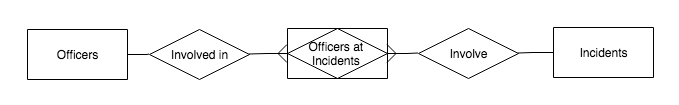
Here is what a many-to-many relationship between two entities, with one associative entity in between, might look like in an ERD:
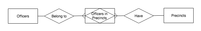
Above: This ERD indicates that one officer may belong to multiple precincts (over time), and that one precinct may house multiple officers.
The El Grito Example below shows what an ERD for a complete data model might look like.
Going through the process of drafting an entity-relationship diagram is very useful. It helps you see and refine the overall structure of your data. You will probably go through several drafts — and your first draft will likely resemble a messy cobweb. But from there, you can see where you might have made some logical errors, where relationships do or don’t really exist, and where you can simplify.
Using an ERD, here are some tips for refining the relationships in your data model:
- Make sure the relationships in your diagram reflect real-life direct relationships between the entities. You might end up going back to Step 1, and refining your entities.
- State the relationship in “subject-verb-object” form out loud, following the one-to-many cardinal direction, and see if it makes logical sense, e.g. “One incident is documented by many Images.”
- Avoid circular references. This looks like a “loop” in your ERD, where the relationship lines (following the cardinal direction of one-to-many) allow one entity to “reach” other entity from two different directions. This creates a logical problem for a database. You have to find a way to eliminate the loop that makes sense in real-life.
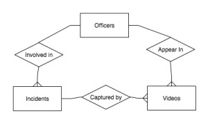
Above: Example of a circular reference you want to avoid. Here, there are two ways for “Officer” records to be associated with “Video” records (directly, and indirectly via “Incidents”). This will cause errors.
Berkeley Copwatch Example
During the workshop with Berkeley Copwatch, we started sketching out a “back-of-the-napkin” ERD using paper and ribbon taped up to a wall. From this visualization and notes from the workshop, we are currently creating a more elaborated ERD.

El Grito Example
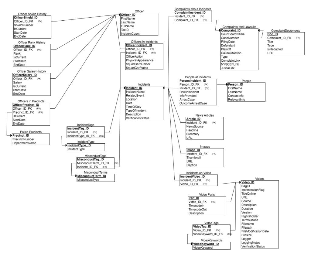
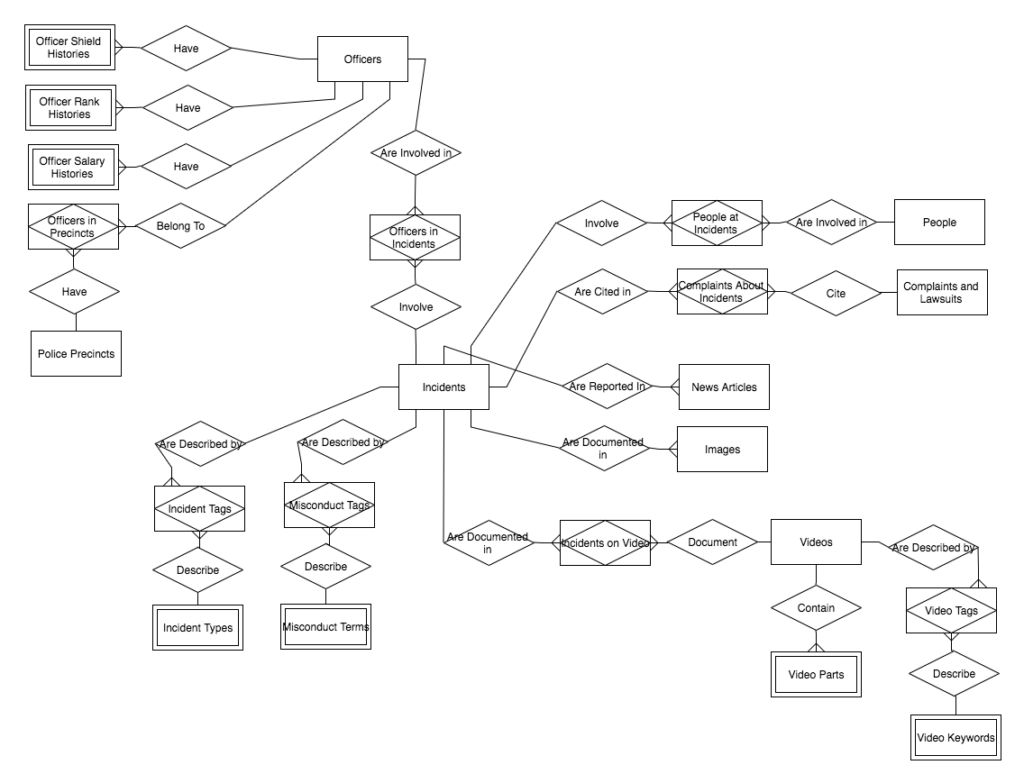
Here is (the most recent draft of) an entity-relationship diagram for the El Grito project:
In the first draft of our ERD (not shown), we saw everything as related to everything else, which created problematic circular references. The issue these loops presented was made clear when we tried to test the data model in the next step, and the test database returned incorrect data.
A rule-of-thumb in creating an entity-relationship model is that starting from any given entity, you should be able to follow a path in any one-to-many direction (remember that relationships that involve associative entities are bidirectional) to an end-point. If you can go in an endless circle anywhere in your model, you may cause problems with your data when you try to make a database.
As you can see in the ERD above, we decided that Videos would directly relate only to Incidents, and not to Officers or People (even though in real-life, officers and people do appear in the videos). Instead, Videos would relate to Officers and People indirectly via Incidents. This prevents a circular reference and still reflects real-life relationships — videos show incidents, and incidents involve officers and people.
Note that we could have come up with a different relationship model, and it would have been fine as a data model (as long as it still reflected real-life relationships). Our model looks the way it does because it reflects the analysis the team was actually doing, which was centered on describing Officers and Incidents.
3.3 Creating a Relational Schema with Primary and Foreign Keys
This step is where we start to go from the abstract to real-life implementation (of a relational database). In a relational database, abstract entities become tables. Attributes become fields. And relationships are created using primary and foreign keys.
| Concept | In a Database |
| Entity | Table |
| Attribute | Field |
| Relationship | Primary and Foreign Keys |
A primary key is a special attribute of an entity/table whose only purpose is to uniquely identify each record in the table; basically, it’s an ID number for each row in a table. For example, the primary key of this table is in red:
INCIDENTS
| ID | Date | Location | Type of Incident |
| 1 | 2016-01-31 | Sunset Park | Search |
| 2 | 2016-01-31 | Fort Greene | Arrest |
| 3 | 2014-03-10 | Sunset Park | Harassment |
Every table must have a primary key. Good primary keys should:
- Be unique and simple, like a sequential number.
- Be sufficiently (or endlessly) generatable, i.e. you shouldn’t run out of available IDs.
- Not change over time.
- Not be actual data you’re trying to track, or based on that data. For example, in the table above, do not use the date as the basis for an ID. The primary key should be meaningless outside of uniquely identifying the record.
A foreign key is just a primary key from another table, and it’s how relationships are made in a database. For example, if I have an News Article table, and I want to relate an News Article record to one of the Incident records above, I would create a foreign key for Incident ID in my News Article table:
NEWS ARTICLES
| ID | News Source | Date | URL | Incident ID
(Foreign Key) |
| 1 | New York Times | 2014-03-11 | nytimes.com/123 | 3 |
| 2 | New York Daily News | 2016-02-01 | dailynews.com/456 | 1 |
Working off your entity-relationship diagram, you can now draw a relationship schema (you can do this in ERDPlus too) to show the primary and foreign keys and attributes in your data model. To get a sense of what this looks like, see the El Grito example below.
Some tips on creating primary and foreign keys:
- Give each and every entity / table a primary key.
- Give the primary keys simple names, like “Incident_ID”.
- To create a one-to-many relationship, create a foreign key in the entity that is on the “many” or “child” side of the relationship. For example, if one Incident can be reported in many News Articles, create a foreign key in the News Articles table.
- Some people like to give foreign keys the same name as the primary keys they are connected to (i.e. “Incident_ID” in the Incidents Table is also “Incident_ID” in the News Article table). Others like making foreign keys more easily recognizable, by adding something like “FK” to the foreign key’s name, e.g. “Incident_ID_FK”.
El Grito Example
Here is the relationship schema for the data model, showing only the primary and foreign keys:
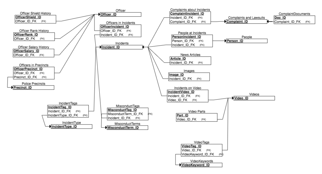
Here is a relational schema diagram with keys and attributes: